PyOpenNI and OpenCV

In my last post I gave an example of how to use OpenKinect to get a depth stream which can be manipulated with OpenCV in Python. This example uses PyOpenNI instead, which is more powerful as it exposes useful OpenNI functionality.

The gist of this example is that PyOpenNI abstracts the depth map behind a DepthMap object and for OpenCV we need to turn that into a numpy array. As DepthMap can be iterated over, the most obvious solution is to just call numpy.asarray with the depth map; however, I’ve found that to be far too slow for practical use.

A much faster way is to use the older raw depth stream functions from PyOpenNI’s DepthGenerator class. These functions – get_raw_depth_map and get_raw_depth_map_8 – return byte strings of 16 and 8 bits per pixel, respectively. Numpy can create an array from these byte strings significantly faster than just calling numpy.asarray with the DepthMap object.

from openni import *
import numpy as np
import cv2

# Initialise OpenNI
context = Context()
context.init()

# Create a depth generator to access the depth stream
depth = DepthGenerator()
depth.create(context)
depth.set_resolution_preset(RES_VGA)
depth.fps = 30

# Start Kinect
context.start_generating_all()
context.wait_any_update_all()

# Create array from the raw depth map string
frame = np.fromstring(depth.get_raw_depth_map_8(), "uint8").reshape(480, 640)

# Render in OpenCV
cv2.imshow("image", frame)

In this example a single frame is taken from the Kinect depth stream and turned into an OpenCV-compatible numpy array. This could be useful as a starting point for a Kinect finger tracker because it allows OpenNI’s skeleton and hand tracking functionality to be used alongside OpenCV. As an example, OpenNI could be used to track current hand position so that OpenCV knows which region of the depth map (or rgb stream – this code is easily modifiable to use that instead) contains a hand. Computer vision techniques could then be used to look for fingers in that region – removing the need to try and segment using colour when looking for hands in a normal rgb image.
OpenKinect Python and OpenCV

I’ve spent the past day or so messing around with Kinect and OSX, trying to find a nice combination of libraries and drivers which works well – a more difficult task than you’d imagine! Along the way I’ve found that a lot of these libraries have poor or no documentation.

Here I’m sharing a little example of how I got OpenKinect and OpenCV working together in Python. The Python wrapper for OpenKinect gives depth data as a numpy array which conveniently is the datatype used in the cv2 module.

import freenect
import cv2
import numpy as np

"""
Grabs a depth map from the Kinect sensor and creates an image from it.
"""
def getDepthMap():	
	depth, timestamp = freenect.sync_get_depth()

	np.clip(depth, 0, 2**10 - 1, depth)
	depth >>= 2
	depth = depth.astype(np.uint8)

	return depth

while True:
	depth = getDepthMap()

	blur = cv2.GaussianBlur(depth, (5, 5), 0)

	cv2.imshow('image', blur)
	cv2.waitKey(10)

Here the getDepthMap function takes the depth map from the Kinect sensor, clips the array so that the maximum depth is 1023 (effectively removing distance objects and noise) and turns it into an 8 bit array (which OpenCV can render as grayscale). The array returned from getDepthMap can be used like a grayscale OpenCV image – to demonstrate I apply a Gaussian blur. Finally, imshow renders the image in a window and waitKey is there to make sure image updates actually show.

This is by no means a comprehensive guide to using freenect and OpenCV together but hopefully it’s useful to someone as a starting point!

First Impressions of Pebble

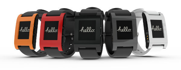
pebble-watch-5-colors-w


Smart-watches seem to be quite trendy at the moment, no doubt thanks to the Kickstarter success of Pebble showing that there’s growing interest in wearable computers. I’m quite interested in wearable technology and have thrown together really low-fidelity prototypes of wearables in the past for research projects, using elastic bands, velcro and old watch straps. To bring my research back to the twenty-first century we picked up a Pebble, mostly just to see what it can do. In this post I ramble about my first impressions of Pebble and talk about what I want from a “smart”-watch.

I’ve been wearing it for the past few days now – pretty much from when I wake up to when I go to sleep. My initial impression is that the watch needn’t even have a display – the things I find it most useful for (and the things it does the best) are all non-visual.

I find Pebble to be of limited use as an input device; however, the hardware buttons are a nice size and are easy to use without looking at the watch. I use my phone for music whilst driving and have never been able to skip tracks, although Pebble now makes this possible. It’s easy to keep one hand on the steering wheel and use the other to press the “next track” button on the watch, without taking my eyes off the road.

The other thing I find Pebble useful for is knowing when I have notifications on my phone to attend to. This is largely thanks to the vibrotactile alerts – the display itself is of limited use because of its small size. While the vibrotactile notifications are useful, they lack customisation (although I hope this is something which changes in future iterations of the Pebble software). All notifications seem to have the same vibrotactile pattern, so it’s impossible to tell the difference between a text and an email without looking at the display.

With these two uses – hardware buttons to control another device and vibrotactile notifications – in mind I have to wonder if smart-watches even need a display. I’m completely unconvinced by the clunky and awkward user interface the watch provides and would much prefer a “normal” watch which connects to my phone (or other devices) so I can remotely control them and receive notifications from them.

mens-proximity-watch-citizen

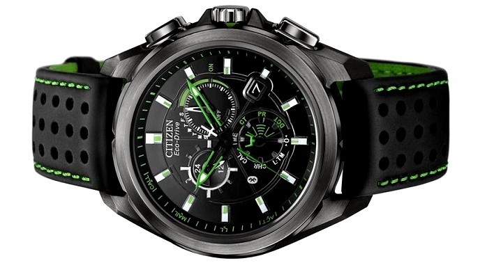
Which brings me to Citizen’s Proximity watch (above). This is the first “smart-watch” I’ve seen which still looks like a normal watch. It connects to smartphones and delivers notifications using vibrotactile feedback and simple visual feedback on the watch-face. When a notification is delivered, one of the watch-hands jumps to a text label on the display, showing the notification type. If only those two chunky buttons could also be put to good use!

Network status in Android KitKat

nexus five phone

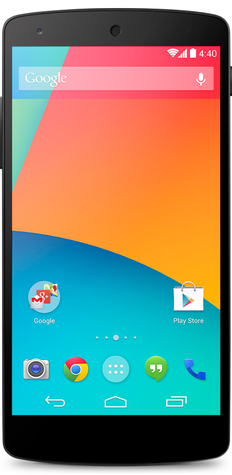
Android KitKat, the most recent version of the Android operating system, has had a bit of a facelift. Gone are the solid black backgrounds and blue accents which defined Android’s aesthetic, replaced by a much cleaner look. On the home screen (pictured), transparency and white icons create a simpler appearance.

While this improves the appearance of Android (in my opinion) it also takes away a subtle visual cue which I found really helpful. In the old Android colour scheme, the network connection icon changed from blue to grey when the internet connection was down. With a rather unreliable router at home, this subtle cue let me know the difference between having to reboot the router and just having to wait a while longer for things to load; because when you live in a rural area, the internet is just terrible.

It’s a minor quibble, I know, but I’ll miss that helpful little indication of network status. It’s a shame when function is sacrificed for form, no matter how insignificant it may seem.

Heuristics for smarter Leap Motion tracking

Leap Motion is quite easy to develop for but I find that hand and finger tracking can be tricky – especially for more precise gesture control. I’ve been doing some development with Leap that requires precise positioning (~mm accuracy needed) with multiple fingers. In this post I run through a few strategies I use to try and improve my Leap applications.

1) Track hand and finger identifiers

Each Finger and Hand object has a unique identifier which should remain consistent between frames, so long as the object continues to be tracked. If you can make a reasonable assumption about which finger(s) the user is intending to use for interaction, you can look for a specific identifier to find the finger(s) of interest, ignoring anything else in the frame. I find that when extending their index finger for interaction, most users tend to hold their thumb out unwittingly; which Leap detects, of course.

I use a simple heuristic to try address this issue: pick the finger with the smallest z-coordinate (furthest forward) and track its identifier in future frames. When I want to track multiple fingers for interaction, I make sure those fingers are attached to the hand whose identifier I’m tracking. This rejects other unattached fingers in the field of view, e.g. the cylindrical lights in my office at university! (Seriously…)

2) Check finger lengths

Sometimes Leap sees your knuckles in a closed fist and reports them as fingers. The looser the grip, the worse the problem. Checking that the length of each finger is above a threshold length can help you reject misclassified knuckles and clenched fingers. A threshold of 2 cm or thereabouts should be fine; any longer and you risk rejecting small fingers or fingers which are fully extended but Leap just isn’t tracking properly.

3) Look at direction vectors for unlikely values

The biggest problem I have with Leap is that it picks up fingers in a closed fist. Looking at the debug visualiser, I tend to see fingers pointing upwards through the fist, rather than an accurate representation of a finger in a clenched fist. These “phantom” fingers tend to have extreme y values in the direction vector (> 0.6). Through observation of some of my users I’ve also noticed that when using a certain hand pose for input, “inactive” fingers are left to hang down; which Leap picks up perfectly. These fingers typically point downwards, with a high y value in the direction vector (< -0.6).

A heuristic I use to reject “phantom” fingers and fingers the user probably doesn’t want to use for input is to take the absolute y value from the direction vector and ignore the finger if this value exceeds a threshold. I use a threshold around 0.4. A limitation of this heuristic is that the user has to keep their hand quite flat. To address this, you could instead measure finger direction relative to the hand orientation and then apply the threshold.

Summary

Sometimes Leap gives crap data and we also can’t expect our users to keep a perfectly clenched fist. A few simple checks on each frame update can help us reject fingers which either don’t exist or weren’t intended to be part of the interaction.

Leaping into motion

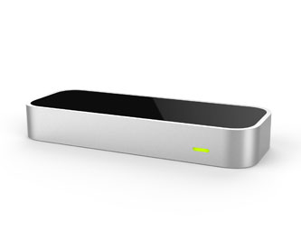
leapmotionMy Leap Motion arrived today. I’ve been working with a development version of the hardware for a couple of months now but I was excited to see what improvements the retail version brought. Other than the obvious aesthetic differences (I’m a fan of the brushed aluminium look!), the retail version has a wider field of view. While this doesn’t affect use of the device much, it does mean that it’s less likely to lose sight of your hands when you move too far away whilst close to the desk. Based on the diagnostic visualiser, it also seems to be more accurate and deals with hand rotation better (although this is likely a software rather than hardware improvement).

Having tried some of the apps in the Airspace app store I’m surprised at the large variety of pointing and selection mechanisms being used by developers. Using the finger as a pointer to control the cursor seems easy enough (although it quickly becomes fatiguing after extended periods!), and most developers seem consistent in how they implement this. Getting the control:display gain correct is going to be a key challenge, as some apps require only the most subtle of finger movements to send the cursor flying accidentally. Smoothing the cursor position (e.g. using a Kalman filter) would help to deal with cursor jitter and unexpected movement.

There are a variety of selection methods being used, including finger poke and tap (two gestures recognised by the base SDK), dwell, and opening the hand. The latter selection gesture is used in the Jazz Hands game and works surprisingly well. While pointing to control a cursor, the user can make a selection by opening their hand up. While there is a little inadvertent movement of the cursor as a result of the gesture, it doesn’t require any direct movement of the pointing finger.

I’m not a fan of the poke and tap gestures but that might just be because I’ve yet to try a good implementation of them. I’ve implemented my own recogniser for tap gestures a couple of weeks ago and know how challenging it can be to get it feeling “right”.

Dwell selection is generally very accurate and I think that this is going to be one of the best selection methods for Leap going forward. This is largely because it allows the user to leap into an app (a terrible pun, I know) without having to figure out how to make selections. The immediacy of the visual feedback makes it obvious that by remaining over a button, something is taking place.

I’m excited about the future of Leap and other gesture interfaces because they offer the potential to create new ways of interacting with computers. It’s not the future, but it’s a step in the right direction.

Balanced Latin Squares in C# and R

For a recent experiment I used the method presented here to generate a balanced latin square for selecting participant condition orders. Rather than do this manually, I wrote a couple of functions to do this automatically for squares of any size. Here’s an implementation in both C# and R!

C#

public static int[,] GetLatinSquare(int n)
{
    // 1. Create initial square.
    int[,] latinSquare = new int[n, n];

    // 2. Initialise first row.
    latinSquare[0, 0] = 1;
    latinSquare[0, 1] = 2;

    for (int i = 2, j = 3, k = 0; i < n; i++)
    {
        if (i % 2 == 1)
            latinSquare[0, i] = j++;
        else
            latinSquare[0, i] = n - (k++);
    }

    // 3. Initialise first column.
    for (int i = 1; i <= n; i++)
    {
        latinSquare[i - 1, 0] = i;
    }

    // 4. Fill in the rest of the square.
    for (int row = 1; row < n; row++)
    {
        for (int col = 1; col < n; col++)
        {
            latinSquare[row, col] = (latinSquare[row - 1, col] + 1) % n;

            if (latinSquare[row, col] == 0)
                latinSquare[row, col] = n;
        }
    }

    return latinSquare;
}

R

LatinSquare <- function(n) {
  # 1. Create initial square.
  sq <- matrix(0, n, n)

  # 2. Initialise first row.
  sq[1, 1] <- 1
  sq[1, 2] <- 2

  j <- 3
  k <- 0

  for (i in 3:n) {
    if (i %% 2 == 0) {
      sq[1, i] <- j
      j <- j + 1
    } else {
      sq[1, i] <- n - k
      k <- k + 1
    }
  }

  # 3. Initialise first column.
  for (i in 2:(n+1)) {
    sq[i - 1, 1] <- i - 1
  }

  # 4. Fill in the rest of the square.
  for (row in 2:n) {
    for (col in 2:n) {
      sq[row, col] <- (sq[row - 1, col] + 1) %% n

      if (sq[row, col] == 0) {
        sq[row, col] = n
      }
    }
  }

  return (sq)
}


Creating Tactons in Pure Data

What are Tactons?

Tactons are “structured tactile messages” for communicating non-visual information. Structured patterns of vibration can be used to encode information, for example a quick buzz to tell me that I have a new email or a longer vibration to let me know that I have an incoming phone call.

Vibrotactile actuators are often used in HCI research to deliver Tactons as these provide a higher fidelity of feedback than the simple rotation motors used in mobile phones and videogame controllers. Sophisticated actuators allow us to change more vibrotactile parameters, providing more potential dimensions for Tacton design. Whereas my previous example used the duration of vibration to encode information (short = email, long = phone call), further information could also be encoded using a different vibrotactile parameter. Changing the “roughness” of the feedback could be used to indicate how important an email or phone call is, for example.

How do we create Tactons?

Now that we know what Tactons are and what they could be used for, how do we actually create them? How can we drive a vibrotactile actuator to produce different tactile sensations?

Linear and voice-coil actuators can be driven by providing a voltage but, rather than dabble in electronics, the HCI community typically uses audio signals to drive the actuator. A sine wave, for example, produces a smooth and continuous-feeling sensation. For more information on how audio signal parameters can be used to create different vibrotactile sensations, see [1], [2] and [3].

Tactons can be created statically using an audio synthesiser or a sound editing program like Audacity to generate sine waves, or can be created dynamically using Pure Data. The rest of this post is going to be a quick summary of Pure Data components which can be used in creating vibrotactile feedback in real-time. I’ve just provided an overview of the key components which I use when creating tactile feedback. With the components discussed, the following vibrotactile parameters can be manipulated: frequency, spatial location, amplitude, “roughness” (with amplitude modulation) and duration.

Tactons with Pure Data components

osc~ Generates a sine-wave. First inlet or argument can be used to set the frequency of the sine-wave, e.g. osc~ 250 creates a 250 Hz signal.

dac~ Audio output. First argument specifies the number of channels and each inlet is used to send an incoming signal to that channel, e.g. dac~ 4 creates a four-channel audio output. Driving different actuators with different audio channels can allow vibration to be encoded spatially.

*~ Multiply signal. Multiplies two signals to produce a single signal. Amplitude modulation (see [2] and [3] above) can be used to create different textures by multiplying two sine waves together. Multiplying osc~ 250 with osc~ 30 creates quite a “rough” feeling texture. This can also be used to change the amplitude of a signal. Multiplying by 0 silences the signal. Multiplying by 0.5 reduces amplitude by 50%. Tactons can be turned on and off by multiplying the wave by 1 and 0, respectively.

delay Sends a bang after a delay. This can be used to provide precise timings for tacton design. To play a 300 ms vibration, for example, an incoming bang could send 1 to the hot inlet of *~, enabling the tacton. Sending that same bang to delay 300 would send a bang after 300 ms, which could then send 0 to the cold inlet of *~, ending the tacton.

phasor~ Creates a ramping waveform. Can be used to create sawtooth waves. This tutorial explains how this component can also be used to create square waveforms.

Method Profiling in Android

I’ve recently been using the Android implementation of OpenCV for real-time computer vision on mobile devices. Computer vision is computationally expensive – especially when you’re working with a camera stream in real-time. In trying to speed up my object tracking algorithm I used Android’s method profiler to analyse the time spent in each function, hoping to identify potential areas for optimisation. This makes an interesting little case study and example of how to use Android’s profiling tools.

How do I enable profiling?
Traceview is part of the Eclipse ADT. Whilst in the DDMS perspective, method profiling can be enabled by selecting a debuggable process and clicking the button circled below. To stop profiling, click the button again. After the profiler is stopped, a Traceview window will appear.


Interpreting Traceview output


The image above was my first method trace, capturing around seven seconds of execution and thousands of method invocations. Each row in the trace corresponds to a method (ordered by CPU usage by default). Selecting a row expands that method, showing all methods invoked from within that method. Again, these are ordered by their CPU usage.

Optimisation using profile data
Using the above example, we can see that my object tracking algorithm spends most of its time waiting for four methods to return: Imgproc.pyrDown, MainActivity.blobUpdate, Imgproc.cvtColor and VideoCapture.retrieve. The pyrDown method downsamples an image matrix whilst applying a Gaussian blur filter. The blobUpdate method is a callback I use to give updates on a tracked object. The cvtColor method converts the values in a matrix to those of another colour space. The retrieve method captures a frame from the device camera.

The latter two methods are crucial to my object tracking algorithm, as I need to call retrieve to get images from the camera and cvtColor is used to convert from RGB to HSV colour space, as it is better to perform colour thresholding this way. The former two, however, can potentially be optimised.

From this trace I’ve already identified a redundant yet expensive method call: pyrDown. 30% of the time spent in the processFrame method is spent waiting for pyrDown to return. I was using this function to downsample an image from the camera to 240×320, as a smaller image can be processed faster. Instead, this call can be eliminated by requesting 240×320 images from the camera.

In the blobUpdate method I send updates about the location of the tracked object and its size. I maintain a short history of these readings and use dynamic time warping to detect gesture input. By expanding the trace for this method I see that my gesture classification function is taking the most time to execute. As dynamic time warping, by design, finds alignments between sequences of different lengths, I can reduce the frequency of checking for gestures. By only checking for gestures in every second call of blobUpdate, I effectively half the amount of time spent checking for gestures. This still maintains a high recognition rate by virtue of dynamic time warping’s resilience to differences in alignment length.

Conclusion
The case study in this post demonstrates how method profiling can be used to identify potential areas for optimisation; something which can be particularly beneficial in a computationally expensive application. By profiling a few seconds of execution of a computer vision algorithm I was able to capture data about thousands of method invocations. From the trace data I identified a redundant method call which accounted for 30% of my algorithm’s execution time and identified an optimisation to the second most expensive method call.